Compare All UT Models
UT75A/UT55A/UT52A/UT35A/UT32A
-
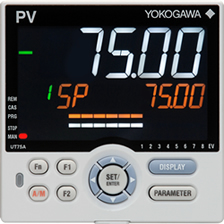
UT75A
-
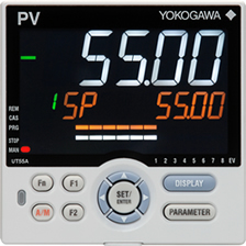
UT55A
-
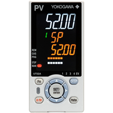
UT52A
-
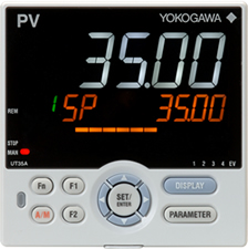
UT35A
-
UT32A
Size |
||||
|---|---|---|---|---|
| 1/4 DIN | 1/4 DIN | 1/8 DIN | 1/4 DIN | 1/8 DIN |
Number of Control Loops (Maximum) |
||||
| 2 | 1 | 1 | 1 | 1 |
Control Scan Period (msec) |
||||
| Choice 50/100/200 |
Choice 50100/200 |
Choice 50/100/200 |
200 | 200 |
Display Function |
||||
Number of PV Display Digits |
||||
| 5 | 5 | 5 | 5 | 5 |
Active Color PV Display Function |
||||
| ○ | ○ | ○ | ○ | ○ |
Guide Scroll Display Function |
||||
| ○ | ○ | ○ | ○ | ○ |
Message Display Function |
||||
| ○ | ○ | ○ | ○ | ○ |
Bar graph display (Number) |
||||
| ○(2) | ○(2) | ○(2) | ○(1) | ○(1) |
PV Input Indication Accuracy (% of F.S.) |
||||
| 0.1 | 0.1 | 0.1 | 0.1 | 0.1 |
PV Input Type |
||||
| TC, RTD (3-wire), RTD (4-wire), mV, V, mA |
TC, RTD (3-wire), RTD (4-wire), mV, V, mA |
TC, RTD (3-wire), RTD (4-wire), mV, V, mA |
TC, RTD (3-wire), mV, V, mA |
TC, RTD (3-wire), mV, V, mA |
Number of Analog Inputs (Maximum) |
||||
| 4 | 4 | 2 | 1 | 1 |
Number of SPs (PIDs) (Maximum) |
||||
| 20 | 8 | 8 | 4 | 4 |
Number of Control Modes (Maximum) |
||||
| 9 | 8 | 8 | 1 | 1 |
Number of Control Types (Maximum) |
||||
| 8 | 8 | 8 | 5 | 5 |
Control Output Type |
||||
| Relay Contact Output, Voltage pulse output, Current output |
Relay Contact Output, Voltage pulse output, Current output |
Relay Contact Output, Voltage pulse output, Current output |
Relay Contact Output, Voltage pulse output, Current output |
Relay Contact Output, Voltage pulse output, Current output |
Control Output Algorithm |
||||
| ON/OFF, PID (Continuance, Time Proportion), Position proportional, Heating/cooling |
ON/OFF, PID (Continuance, Time Proportion), Position proportional, Heating/cooling |
ON/OFF, PID (Continuance, Time Proportion), Position proportional, Heating/cooling |
ON/OFF, PID (Continuance, Time Proportion), Position proportional, Heating/cooling |
ON/OFF, PID (Continuance, Time Proportion), Position proportional, Heating/cooling |
Number of Analog Outputs (Maximum) |
||||
| 3 | 3 | 3 | 2 | 2 |
Number of Digital Inputs (Maximum) |
||||
| 8 | 9 | 5 | 7 | 4 |
Number of Alarms |
||||
| 8 | 8 | 8 | 4 | 4 |
Number of Digital Outputs (Maximum) |
||||
| 8 | 18 | 5 | 8 | 5 |
Communication |
||||
| RS-485 Ethernet CC-Link PROFIBUS-DP DeviceNet |
RS-485 Ethernet CC-Link PROFIBUS-DP DeviceNet |
RS-485 CC-Link |
RS-485 Ethernet CC-Link PROFIBUS-DP DeviceNet |
RS-485 CC-Link |
Various Function |
||||
Quick Setting Function |
||||
| ○ | ○ | ○ | ○ | ○ |
Split Computation Output Function |
||||
| ○ | ○ | ○ | - | - |
Ratio and Square Root Extraction Function |
||||
| ○ | ○ | ○ | - | - |
Remote SP Function |
||||
| ○ | ○ | ○ | - | - |
24 V DC Loop Power Supply Function |
||||
| - | ○ | ○ | ○ | ○ |
Heater Break Alarm Function |
||||
| - | ○ (Standard type) |
○ (Standard type) |
○ (Standard type or Heating/cooling type) |
○ (Standard type or Heating/cooling type) |
Ladder Sequence Function (Number of max. steps) |
||||
| 1000 | 500 | 500 | 300 | 300 |
Other specifications |
||||
Power Supply AC100 V to 240 V |
||||
| ○ | ○ | ○ | ○ | ○ |
Power Supply AC/DC 24V |
||||
| ○ | ○ | ○ | ○ | ○ |
Dust and waterproof Level of Front Panel |
||||
| NEMA4 *1 (IP66) |
NEMA4 *1 (IP66) |
NEMA4 *1 (IP66) |
NEMA4 *1 (IP66) |
NEMA4 *1 (IP66) |
Configuration Tool Via Light-loader Communication |
||||
| ○ | ○ | ○ | ○ | ○ |
Configuration Tool Via Maintenance Port Communication |
||||
| ○ | ○ | ○ | ○ | ○ |
Configuration Tool Via RS-485/Ethernet communication |
||||
| ○/○ | ○/○ | ○/- | ○/○ | ○/- |
- * 1: Hose down test only.
The table above includes specifications of the standard models only.